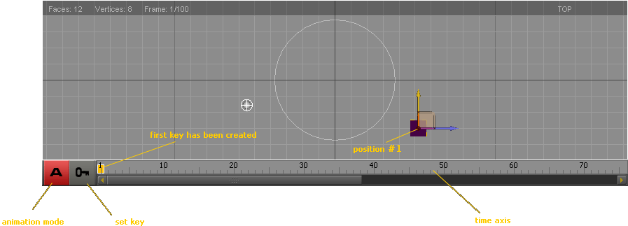
Animation in the 3D Esquimo runs on the basis of time measured in frames. In short, the essence of the animation process is about setting keys for objects in different places on the timeline - frames. The keys are objects that tell which parameters belong to the object in the frame where the key has been placed, that is, for example, in which position it is in different times during the animation. Name - key - comes from the fact that they are set for each object in the specific situations. For example, if you want the object created by you to move around the perimeter of the triangle, it is sufficient that in the relevant moments of time of the animation you will move this object in places where the vertices of the triangle are placed and put the keys. The trajectory of motion for the animation will be then calculated on the basis of these 3 keys and their properties.
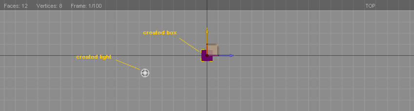
If you have used any other animation software surely you understand the process of keyframing. If you meet that issue for the first time, try to make a simple exercise, that makes the cube moving along a trajectory of the triangle. On this simple animation I will gradually explain the options available for animation.
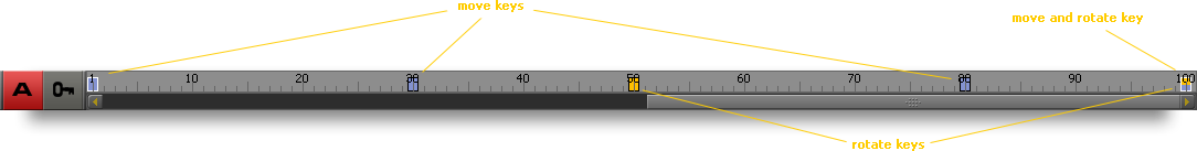
And the modified animation like that - from the frame nr 50 the box should rotate:
| Top view | Perspective view |
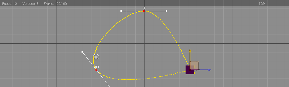
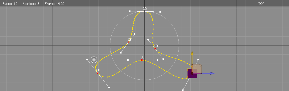
In the "animation" mode keys are modified or added if in the frame there is no keys like that, at each change in the position/rotation/scale of object by the user. For practice, try to modify the trajectory of the cube motion, so it is similar to the one shown below. It is sufficient to move the cube in frames 19, 52, 88 (this is just a proposal, you do not need to choose exactly those frames) closer to the center of the loop, which is formed by the trajectory of motion.
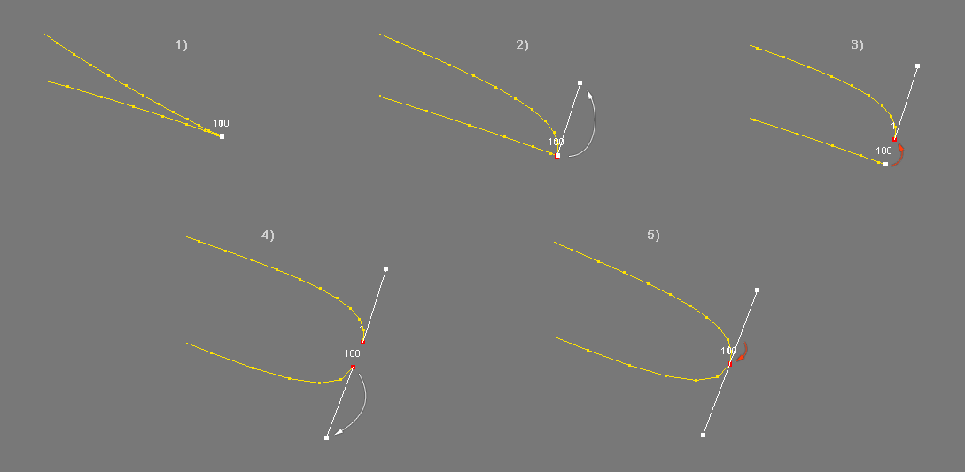
Additionally, you can modify the shape of the trajectory by the handles tangential to the curves in the key frame. You may have trouble with achieving the round trajectory at the point where the first and last frame are, because the handle coincides with a key there. The best thing is to deal with such situations by temporarily postponing one of the keys for a small distance, pulling out handles comfortably and pushing the keys back, so they are in one place. The figure below presents the scheme of conduct:
Animation after the recent changes looks as follows:
| Top view | Perspective view |
"Animation" mode, "Geometry" mode and pivot point in term of above.
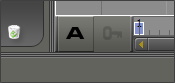
To fully understand principles of animating in Esquimo you need to know te difference between "Animation" and "Geometry" mode. You can switch between them with "A" button right next to begin of time axis.
 |
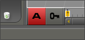 |
| "Geometry" mode | "Animation" mode |
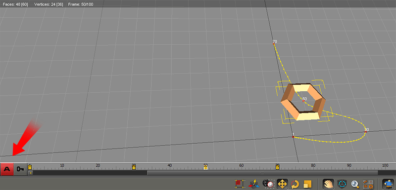
Consider geometry object like torus or box as a container inside of which there is a set of vertices that form the object. When you move/rotate/scale selected object being in "Geometry" mode you actually modify coordinates of particular vertices. It is like changing a mesh structure. It doesn't look like typical mesh deforming but moving/rotating/scaling vertices does deform the mesh in term of its structure. In a such process mesh vertices takes new coordinates. What's important - this kind of modification is not animated. To understand what "Geometry" mode is about, look at this simple animation.
In the "Animation" mode a few "move" keys has been set. The object follows the trajectory is you would expect. Click on the picture to see it in motion.
|
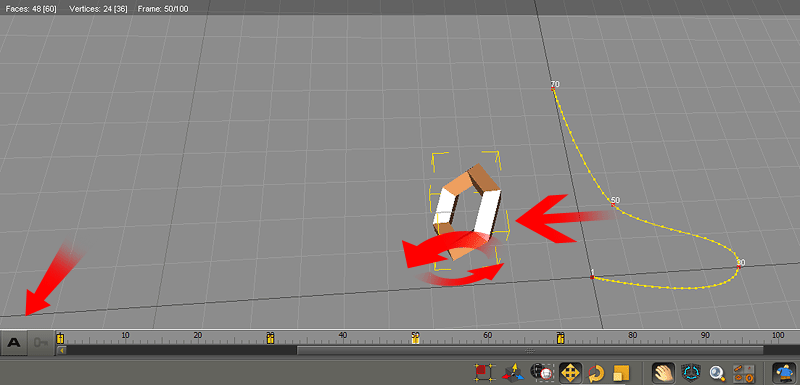
After switching to "Geometry" mode the object has been moved a bit to the left and rotated by 45°. The number of frame in which the modification has been done doesn't matter as it affects all the existing animation. You can take it as constant "shift" and this is the point of using "Geometry" mode. Click on the picture to see the motion after the change.
|
Pivot point
Actually each geometry object in Esquimo has two pivots activated interchangeably for "Geometry" and "Animation" mode. While "Geometry" mode repositioning pivot will affect rotation and scaling in this mode only. Thus it doesn't impact directly on animation. It should be considered as a help tool to make mesh transformation based on rotating/scaling.
Once you switch from one mode to another pivot will change its position (if it was changed in any mode prior). This indicates that from now on you are using other pivot.
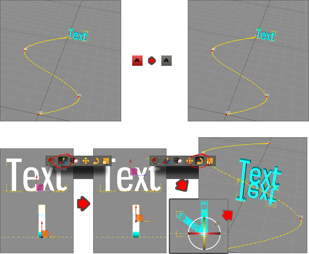
To see the difference in their working let's take a sample use case. Let's say you have got a text animation completed. It moves along some trajectory. To make its vertical mirror reflection duplicate the text object and switch to "Geometry" mode. Then you can set up pivot at bottom line of the duplicated text and rotate it by 180°.
After changes made as shown on the picture above the text object will be traveling with its mirrored copy.
In "Animation" mode pivot does affect rotation and scaling which are performing based on pivot point location - the pivot positioned in "Animation" mode. Let's recreate very simple example. The ball moving along the line and rotating around distant center. The following steps are:
- Being in "Animation" mode set two "move" keys in 1st and 50th frame.
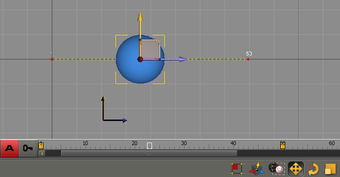
- Click on "Move pivot point" icon and move ball's pivot like on the picture below. You will notice that the entire spline ot trajectory will move as well. This is a consequence of mathematical background within animation mechanism.
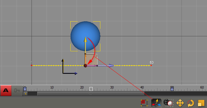
- Active "Rotate object" mode and set the key in first frame and another one in last (50) frame with rotation for Z axis=360° (if you put 720 or any bigger nth of 360 it will look like kind of sprial trajectory). The ball should follow along a curved trajectory which is a result of adding linear and orbital motion of the object. Click on the picture to see in it in motion.
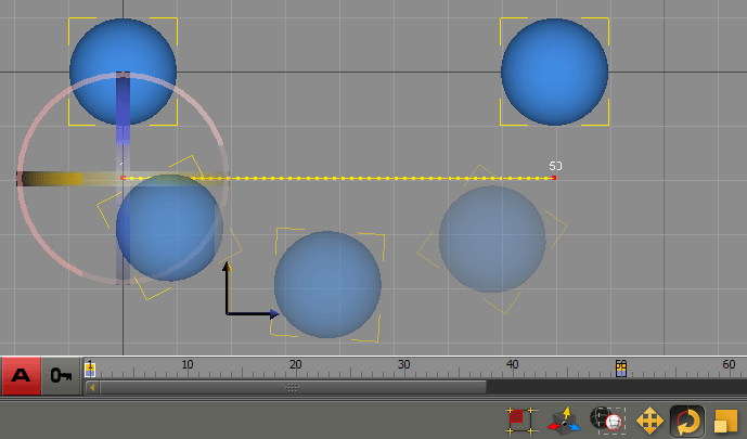
|